After many years, I’ve finally gotten around to automating some antenna system measurements. I spent some time a few years ago trying to isolate my antenna from my house (and my neighbor’s houses) to minimize noise (see John Doty’s excellent Usenet posting about this below), but I never had a real way to measure how effective this has been.
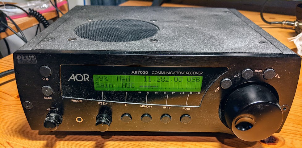
Now thanks to hamlib and it’s Python plug-in binding, gnuplot, and my reliable AOR AR7030+ receiver, I was able to quickly and easily script a way to measure the noise levels across the LF, MF and HF ranges. The graph here shows the first set of runs, with the input grounded, and with my (approximately) 80M quarter wave vertical at mid-day and at sunset.
There’s still lots to do, with both the antenna system and the automation scripts:
- Replace old 50 ohm coax with direct bury, fully shielded 75 ohm coax
- Fix and enhance grounding at antenna and house ends of the coax run
- Install radials at the antenna grounding end
- Have the script automatically bypass the AM and SWBC bands
- Find some way to automatically attach a timestamp to the graphs

At the very least, this is a good way to document the status of the antenna system, so that if anything changes, it can be easily detected. I notice a few interesting things about the plot: There is more energy around the resonance point of the antenna (~3.5 MHz), the upper (20 MHz) and lower (100 kHz) cutoff points of the 1:1 balun are visible, the gap (~12 dB) between the noise floor and when the AGC engages is clearly visible.
Low Noise Antenna Connection

From: jpd@space.mit.edu (John Doty)
Newsgroups: rec.radio.shortwave
Subject: Low Noise Antenna Connection
Date: 26 Nov 1993 16:55:24 GMT

It doesn't take very much wire to pick up an adequate signal for anything but
the crudest shortwave receiver. The difference between a mediocre antenna
system and a great antenna system isn't the antenna itself: it's the way you
feed signals from the antenna to the receiver. The real trick with a
shortwave receiving antenna system is to keep your receiver from picking up
noise from all the electrical and electronic gadgets you and your neighbors
have.

The Problem:

Any unshielded conductor in your antenna/ground system is capable of picking
up noise: the antenna, the "lead-in" wire, the ground wire, etc. Even the
widely recommended cold water pipe ground can pick up noise if it runs a
significant distance before it goes underground

Symptoms of this problem include buzzing noises, especially at lower
frequencies, clicks as appliances are turned on or off, and whines from
motorized devices. Sometimes the problem can be reduced by running the radio
from batteries.

The Solution:

The solution is to keep the antenna as far as possible from houses, power
lines, and telephone lines, and to use a shielded (coaxial) transmission line
to connect it to the receiver. To get this to work well, two problems must
be avoided: noise currents on the shield must be kept away from the antenna
and, if you want to listen to a wide range of frequencies, the cable must be
coupled to the antenna in a non-resonant way.

You can keep noise currents away from the antenna by giving them a path to
ground near the house, giving antenna currents a path to ground away from the
house, and burying the the coaxial cable from the house to the antenna.
Resonance can be avoided by coupling the antenna to the coaxial cable with a
transformer.

Construction:

My antenna and feed system are built with television antenna system
components and other common hardware. These parts are inexpensive and easily
obtainable in most places.

The transformer is built around a toroid extracted from a TV "matching
transformer". If you're a pack rat like me, you have a few in your basement:
you typically get one with every TV or VCR (or you can buy one). Pop the
plastic case off and snip the wires from the toroid (it looks either like a
tiny donut, or a pair of tiny donuts stuck together). The transformer
windings should be made with thin wire: I use #32 magnet wire. The primary
is 30 turns while the secondary is 10 turns. For a one-hole toroid, count
each passage of the wire down through the hole as one turn. For a two-holer
each turn is a passage of the wire down through the right hole and up
through the left.

Mount the transformer in an aluminum "minibox" with a "chassis mount" F
connector for the coax cable and a "binding post" or other insulated terminal
for the antenna. Ground one end of each winding to the aluminum box. Solder
the ungrounded end of the primary to the antenna terminal, and solder the
ungrounded end of the secondary to the center conductor of the coax connector.

Drive a ground stake into the earth where you want the base of your antenna
to be (well away from the house). Mount the transformer box on the ground
stake: its case should make good contact with the metal stake. Drive another
ground stake into the earth near the place where you intend for the cable to
enter the house. Mount a TV antenna "grounding block" (just a piece of metal
with two F connectors on it) to the stake by the house. One easy way to
attach hardware to the ground stakes is to use hose clamps.

Take a piece of 75 ohm coaxial cable with two F connectors on it (I use
pre-made cable assemblies), connect one end to the transformer box, the
other end to the grounding block. Bury the rest of the cable. Finally, attach
a second piece of 75 ohm coax to the other connector on the grounding block
and run it into the house. Use waterproof tape to seal the outdoor connector
junctions.

Attach one end of your antenna to the antenna terminal on the transformer box
and hoist the other end up a tree or other support(s) (don't use the house
as a support: you want to keep the antenna away from the house). My antenna
is 16 meters of #18 insulated wire in an "inverted L" configuration supported
by two trees.

If your receiver has a coaxial input connector, you may need an adapter to
make the connection; in any case, the center wire of the coaxial cable should
attach to the "antenna" connection, and the outer shield should attach to the
"ground" connection.

Multiple grounds and transformer coupling of the antenna should reduce the
danger posed by lightning or other electrostatic discharge, but don't press
your luck: disconnect the coax from the receiver when you're not using it.

How it works, in more detail:

Coaxial cable carries waves in two modes: an "outer" or "common" mode, in
which the current flows on the shield and the return current flows through the
ground or other nearby conductors, and an "inner" or "differential" mode in
which the current flows on the inner conductor and the return current flows
on the shield. Theoretically, outside electromagnetic fields excite only the
common mode. A properly designed receiver is sensitive only to the
differential mode, so if household noise pickup is confined to the common
mode, the receiver won't respond to it.

The "characteristic impedance" of the differential mode is the number you'll
see in the catalog or on the cable: 75 ohms for TV antenna coax. The
characteristic impedance of the common mode depends on the distance of the
line from the conductor or conductors carrying the return current: it varies
from tens of ohms for a cable on or under the ground to hundreds of ohms for
a cable separated from other conductors.

A wire antenna can be approximately characterized as a single wire
transmission line. A single wire line has only a common mode: for #18 wire
30 feet above ground, the characteristic impedance is about 620 ohms. For
heights above a few feet the characteristic impedance depends very little on
the height.

If the impedances of two directly coupled lines match, waves can move from
one line to the other without reflection. In case of a mismatch, reflections
will occur: the magnitude of the reflected wave increases as the ratio of the
impedances moves away from 1. A large reflection, of course, implies a small
transmission. Reflections can be avoided by coupling through a transformer
whose turns ratio is the square root of the impedance ratio.

The basic difficulty with coupling a wire antenna to a coaxial line is that
the antenna's characteristic impedance is a poor match to the differential
mode of the line. Furthermore, unless the line is very close to the ground
the common mode of the line is a good match to the antenna. There is thus a
tendency for the line to pick up common mode noise and deliver it efficiently
to the antenna. The antenna can then deliver the noise back to the line's
differential mode.

Some antenna systems exploit the mismatch between the antenna's characteristic
impedance and the line's characteristic impedance to resonate the antenna.
If the reflection at the antenna/line junction is in the correct phase, the
reflection will add to the signal current in the antenna, boosting its
efficiency. While this is desirable in many cases, it is undesirable for a
shortwave listening antenna. Most shortwave receivers will overload on the
signals presented by a resonant antenna, and resonance enhances the signal
over a narrow range of frequencies at the expense of other frequencies. It's
generally better to listen with an antenna system that is moderately efficient
over a wide frequency range.

In my antenna system, grounding the shield of the line at the ground stakes
short circuits the common mode. The stake at the base of the antenna gives
the antenna current a path to ground (while the transformer directs the energy
behind that current into the coax). Burying the cable prevents any common
mode pickup outside the house, and also attenuates any common mode currents
that escape the short circuits (soil is a very effective absorber of RF energy
at close range). Common mode waves excited on the antenna by incoming signals
pass, with little reflection, through the transformer into differential mode
waves in the coax.

A major source of "power line buzz" is common mode RF currents from the AC
line passed to the receiver through its AC power cord. These currents are
normally bypassed to chassis ground inside the receiver. They thus flow out
of the receiver via the ground terminal. With an unshielded antenna feedline
and a wire ground, the ground wire is a part of the antenna system: these
noise currents are thus picked up by the receiver. On the other hand, with a
well grounded coaxial feed these currents make common mode waves on the coax
that flow to ground without exciting the receiver.

Performance:

A few years ago, I put up a conventional random wire antenna without a coaxial
feed. I was disappointed that, while it increased signal levels over the whip
antenna of my Sony ICF-2001, it increased the noise level almost as much. I
then set up the antenna system described above; in my small yard, the base of
the antenna was only 12 meters from the house. Nevertheless, the improvement
was substantial: the noise level was greatly reduced. This past year I moved
to a place with a roomier yard; with the base of the antenna now 28 meters away.
I can no longer identify any noise from the house.

The total improvement over the whip is dramatic. A few nights ago, as a test
I did a quick scan of the 60 meter band with the whip and with the external
antenna system: with the whip I could only hear one broadcaster
unintelligibly faintly, plus a couple of utes and a noisy WWV signal. With
the external antenna system I could hear about ten Central/South American
domestic broadcast stations at listenable levels. WWV sounded like it was next
door.

I have also tried the antenna system with other receivers ranging from 1930's
consoles to a Sony ICF-SW55. I've seen basically similar results with all.