Years ago, I was impressed by this article, written by John Doty:
Hi! I’m new to this news stuff, but I’ve been listening to shortwave on and off for about 3/4 of my life. I see a lot of discussion of antennas in this forum, so I thought I’d put in my two cents.
It doesn’t take very much wire to pick up an adequate signal for anything but the crudest shortwave receiver. The difference between a mediocre antenna system and a great antenna system isn’t the antenna itself: it’s the way you feed signals from the antenna to the receiver. The real trick with a shortwave receiving antenna system is to keep your receiver from picking up noise from all the electrical and electronic gadgets you and your neighbors have.
The Problem:
Any unshielded conductor in your antenna/ground system is capable of picking up noise: the antenna, the “lead-in” wire, the ground wire, etc. Even the widely recommended cold water pipe ground can pick up noise if it runs a significant distance before it goes underground.
Symptoms of this problem include buzzing noises, especially at lower frequencies, clicks as appliances are turned on or off, and whines from motorized devices. Sometimes the problem can be reduced by running the radio from batteries.
The Solution:
The solution is to keep the antenna as far as possible from houses, power lines, and telephone lines, and to use a shielded (coaxial) transmission line to connect it to the receiver. To get this to work well, two problems must be avoided: noise currents on the shield must be kept away from the antenna, and, if you want to listen to a wide range of frequencies, the cable must be coupled to the antenna in a non-resonant way.
You can keep noise currents away from the antenna by giving them a path to ground near the house, giving antenna currents a path to ground away from the house, and burying the the coaxial cable from the house to the antenna. Resonance can be avoided by coupling the antenna to the coaxial cable with a transformer.
Construction:
My antenna and feed system are built with television antenna system components and other common hardware. These parts are inexpensive and easily obtainable in most places.
The transformer is built around a toroid extracted from a TV “matching transformer”. If you’re a pack rat like me, you have a few in your basement: you typically get one with every TV or VCR (or you can buy one). Pop the plastic case off and snip the wires from the toroid (it looks either like a tiny donut, or a pair of tiny donuts stuck together). The transformer windings should be made with thin wire: I use #32 magnet wire. The primary is 30 turns while the secondary is 10 turns. For a one-hole toroid, count each passage of the wire down through the hole as one turn. For a two-holer, each turn is a passage of the wire down through the right hole and up through the left.
Mount the transformer in an aluminum “minibox” with a “chassis mount” F connector for the coax cable and a “binding post” or other insulated terminal for the antenna. Ground one end of each winding to the aluminum box. Solder the ungrounded end of the primary to the antenna terminal, and solder the ungrounded end of the secondary to the center conductor of the coax connector.
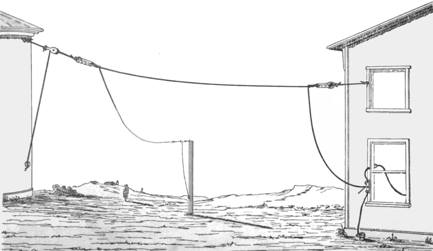
Drive a ground stake into the earth where you want the base of your antenna to be (well away from the house). Mount the transformer box on the ground stake: its case should make good contact with the metal stake. Drive another ground stake into the earth near the place where you intend for the cable to enter the house. Mount a TV antenna “grounding block” (just a piece of metal with two F connectors on it) to the stake by the house. One easy way to attach hardware to the ground stakes is to use hose clamps.
Take a piece of 75 ohm coaxial cable with two F connectors on it (I use pre-made cable assemblies), connect one end to the transformer box, the other end to the grounding block. Bury the rest of the cable. Finally, attach a second piece of 75 ohm coax to the other connector on the grounding block and run it into the house. Use waterproof tape to seal the outdoor connector junctions.
Attach one end of your antenna to the antenna terminal on the transformer box and hoist the other end up a tree or other support(s) (don’t use the house as a support: you want to keep the antenna away from the house). My antenna is 16 meters of #18 insulated wire in an “inverted L” configuration supported by two trees.
If your receiver has a coaxial input connector, you may need an adapter to make the connection; in any case, the center wire of the coaxial cable should attach to the “antenna” connection, and the outer shield should attach to the “ground” connection.
Multiple grounds and transformer coupling of the antenna should reduce the danger posed by lightning or other electrostatic discharge, but don’t press your luck: disconnect the coax from the receiver when you’re not using it.
How it works, in more detail:
Coaxial cable carries waves in two modes: an “outer” or “common” mode, in which the current flows on the shield and the return current flows through the ground or other nearby conductors, and an “inner” or “differential” mode in which the current flows on the inner conductor and the return current flows on the shield. Theoretically, outside electromagnetic fields excite only the common mode. A properly designed receiver is sensitive only to the differential mode, so if household noise pickup is confined to the common mode, the receiver won’t respond to it.
The “characteristic impedance” of the differential mode is the number you’ll see in the catalog or on the cable: 75 ohms for TV antenna coax. The characteristic impedance of the common mode depends on the distance of the line from the conductor or conductors carrying the return current: it varies from tens of ohms for a cable on or under the ground to hundreds of ohms for a cable separated from other conductors.
A wire antenna can be approximately characterized as a single wire transmission line. A single wire line has only a common mode: for #18 wire 30 feet above ground, the characteristic impedance is about 620 ohms. For heights above a few feet the characteristic impedance depends very little on the height.
If the impedances of two directly coupled lines match, waves can move from one line to the other without reflection. In case of a mismatch, reflections will occur: the magnitude of the reflected wave increases as the ratio of the impedances moves away from 1. A large reflection, of course, implies a small transmission. Reflections can be avoided by coupling through a transformer whose turns ratio is the square root of the impedance ratio.
The basic difficulty with coupling a wire antenna to a coaxial line is that the antenna’s characteristic impedance is a poor match to the differential mode of the line. Furthermore, unless the line is very close to the ground, the common mode of the line is a good match to the antenna. There is thus a tendency for the line to pick up common mode noise and deliver it efficiently to the antenna. The antenna can then deliver the noise back to the line’s differential mode.
Some antenna systems exploit the mismatch between the antenna’s characteristic impedance and the line’s characteristic impedance to resonate the antenna. If the reflection at the antenna/line junction is in the correct phase, the reflection will add to the signal current in the antenna, boosting its efficiency. While this is desirable in many cases, it is undesirable for a shortwave listening antenna. Most shortwave receivers will overload on the signals presented by a resonant antenna, and resonance enhances the signal over a narrow range of frequencies at the expense of other frequencies. It’s generally better to listen with an antenna system that is moderately efficient over a wide frequency range.
In my antenna system, grounding the shield of the line at the ground stakes short circuits the common mode. The stake at the base of the antenna gives the antenna current a path to ground (while the transformer directs the energy behind that current into the coax). Burying the cable prevents any common mode pickup outside the house, and also attenuates any common mode currents that escape the short circuits (soil is a very effective absorber of RF energy at close range). Common mode waves excited on the antenna by incoming signals pass, with little reflection, through the transformer into differential mode waves in the coax.
A major source of “power line buzz” is common mode RF currents from the AC line passed to the receiver through its AC power cord. These currents are normally bypassed to chassis ground inside the receiver. They thus flow out of the receiver via the ground terminal. With an unshielded antenna feedline and a wire ground, the ground wire is a part of the antenna system: these noise currents are thus picked up by the receiver. On the other hand, with a well grounded coaxial feed these currents make common mode waves on the coax that flow to ground without exciting the receiver.
Performance:
A few years ago, I put up a conventional random wire antenna without a coaxial feed. I was disappointed that, while it increased signal levels over the whip antenna of my Sony ICF-2001, it increased the noise level almost as much. I then set up the antenna system described above; in my small yard, the base of the antenna was only 12 meters from the house. Nevertheless, the improvement was substantial: the noise level was greatly reduced. This past year I moved to a place with a roomier yard; with the base of the antenna now 28 meters away I can no longer identify any noise from the house.
The total improvement over the whip is dramatic. A few nights ago, as a test, I did a quick scan of the 60 meter band with the whip and with the external antenna system: with the whip I could only hear one broadcaster, unintelligibly faintly, plus a couple of utes and a noisy WWV signal. With the external antenna system I could hear about ten Central/South American domestic broadcast stations at listenable levels. WWV sounded like it was next door.
I have also tried the antenna system with other receivers ranging from 1930’s consoles to a Sony ICF-SW55. I’ve seen basically similar results with all.
I haven’t seen a clearer and more concise description of why the typical do-it-yourself longwire antenna doesn’t work as well as it might. Doty goes on to discuss the importance of grounding in this article:
In your recent post you advised that coax should be grounded at two sites, first at the antenna and then just before entering the house.
Is there an advantage in grounding at more than these sites?
With grounds the most common experience is “the more the merrier”. As you add more, however, you usually reach a diminishing returns (no pun intended) situation where there is no observable improvement: that’s usually a good place to stop. There are also exceptional circumstances where grounding increases noise problems, but these, in my experience, are much rarer than the pundits who preach against “ground loops” seem to think.
Even a semi-quantitative theoretical treatment of grounding in oversimplified situations requires heavy math at RF. Experimentation is thus required even if one has done elaborate calculations. It’s often easier to use the theory as a guide to what to try, and then experiment.
I would also assume that the antenna is grounded when it is connected to the receiver as the outer braid of the coax is in continuity with the receiver chassis.
What’s ground? If connect the shield of my coax (which is grounded outside) to the antenna input of my R8, I hear lots of junk, indicating that there is an RF voltage difference between the coax shield and the R8 chassis. Last night this measured about S5.5, which is about -93 dBm (preamp off, 6KHz bandwidth). That’s a lot of noise: it was 18 dB above my antenna’s “noise floor”, and 26 dB above the receiver’s noise floor.
This sort of disagreement about ground potential is characteristic of electrically noisy environments. The receiver will, of course, respond to any voltage input that differs from its chassis ground. The antenna, on the other hand, is in a very different environment, and will have its own idea of what ground potential is. If you want to avoid noise pickup, you need to deliver a signal, referenced at the antenna to whatever its ground potential is, in such a way that when it arrives at the receiver, the reference potential is now the receiver’s chassis potential.
Coaxial cable represents one way to do this. Coax has two key properties:
The voltage between the inner conductor and the shield depends only on the state of the electromagnetic field within the shield.
The shield prevents the external electromagnetic field from influencing the internal electromagnetic field (but watch out at the ends of the cable!).
So, it’s easy, right? Run coax from the antenna to the receiver. Ground at the antenna end will be whatever the antenna thinks it is, while ground at the receiver end will be whatever the receiver thinks it is. The antenna will produce the appropriate voltage difference at the input side, and the receiver will see that voltage difference uncontaminated by external fields, according to the properties given above.
Unfortunately, it doesn’t quite work that way. It’s all true as far as it goes, but it neglects the fact that the coax can also guide noise from your house to your antenna, where it can couple back into the cable and into your receiver. To see how this works, let me first describe how this noise gets around.
The noise I’m talking about here is more properly called “broadband electromagnetic interference” (EMI). It’s made by computers, lamp dimmers, televisions, motors and other modern gadgets. I have all these things. In many cases, I can’t get them turned off, because it would provoke intrafamilal rebellion. However, even when I turn them off, the noise in the house doesn’t go down very much, because my neighbors all have them too. In any case, one of the worst offenders is my computer, which is such a handy radio companion I’m not about to turn it off.
Some of this noise is radiated, but the more troublesome component of this is conducted noise that follows utility wires. Any sort of cable supports a “common mode” of electromagnetic energy transport in which all of the conductors in the cable are at the some potential, but that potential differs from the potential of other nearby conductors (“ground”). The noise sources of concern generate common mode waves on power, telephone, and CATV cables which then distribute these waves around your neighborhood. They also generate “differential” mode waves, but simple filters can block these so they aren’t normally a problem.
So, let’s say you have a longwire antenna attached to a coaxial cable through an MLB (“Magnetic Longwire Balun” [sic]). Suppose your next door neighbor turns on a dimmer switch. The resulting RF interference travels out his power lines, in through yours, through your receiver’s power cord to its chassis, and out your coaxial cable to your MLB. Now on coax, a common mode wave is associated with a current on the shield only, while the mode we want the signal to be in, the “differential” mode, has equal but opposite currents flowing on shield and inner conductor. The MLB works by coupling energy from a current flowing between the antenna wire and the coax shield into into the differential mode. But wait a second: the current from the antenna flows on the coax shield just like the common mode current does. Does this mean that the antenna mode is contaminated with the noise from your neighbor’s dimmer?
The answer is a resounding (and unpleasant) yes! The way wire receiving antennas work is by first moving energy from free space into a common mode moving along the antenna wire, and then picking some of that off and coupling it into a mode on the feedline. In this case, the common mode current moving along the antenna wire flows into the common mode of the coax, and vice versa. The coax is not just feedline: it’s an intimate part of the antenna! Furthermore, as we’ve seen, it’s connected back through your electrical wiring to your neighbor’s dimmer switch. You have a circuitous but electrically direct connection to this infernal noise source. No wonder it’s such a nuisance!
The solution is to somehow isolate the antenna from the common mode currents on the feedline. One common way to do this is with a balanced “dipole” antenna. Instead of connecting the feedline to the wire at the end, connect it to the middle. Now the antenna current can flow from one side of the antenna to the other, without having to involve the coax shield. Unfortunately, removing the necessity of having the coax be part of the antenna doesn’t automatically isolate it: a coax-fed dipole is often only slightly quieter than an end-fed longwire. A “balun”, a device which blocks common mode currents from the feedline, is often employed. This can improve the situation considerably. Note that this is not the same device as the miscalled “Magnetic Longwire Balun”.
Another way is to ground the coaxial shield, “short circuiting” the common mode. Antenna currents flow into such a ground freely, in principle not interacting with noise currents. The best ground for such a purpose will be a earth ground near the antenna and far from utility lines.
Still another way is to block common mode waves by burying the cable. Soil is a very effective absorber of RF energy at close range.
Unfortunately, none of these methods is generally adequate by itself in the toughest cases. Baluns are not perfectly effective at blocking common mode currents. Even the best balun can be partially defeated if there’s any other unsymmetrical coupling between the antenna and feedline. Such coupling can occur if the feedline doesn’t come away from the antenna at a right angle. Grounds are not perfect either. Cable burial generally lets some energy leak through. A combination of methods is usually required, both encouraging the common mode currents to take harmless paths (grounding) and blocking them from the harmful paths (baluns and/or burial).
The required isolation to reach the true reception potential of the site can be large. According to the measurements I quoted above, for my site the antenna noise floor is 18 dB below the conducted noise level at 10 MHz. 18 dB of isolation would thus make the levels equal, but we want to do better than that: we want the pickup of common mode EMI to be insignificant, at least 5 dB down from the antenna’s floor. In my location the situation gets worse at higher frequencies as the natural noise level drops and therefore I become more sensitive: even 30 dB of isolation isn’t enough to completely silence the common mode noise (but 36 dB is enough, except at my computer’s CPU clock frequency of 25 MHz).
Getting rid of the conducted noise can make a huge difference in the number and kinds of stations you can pick up: the 18 dB difference between the conducted and natural noise levels in the case above corresponds to the power difference between a 300 kW major world broadcaster and a modest 5 kW regional station.
The method I use is to ground the cable shield at two ground stakes and bury the cable in between. The scheme of alternating blocking methods with grounds will generally be the most effective. The ground stake near the house provides a place for the common mode noise current to go, far from the antenna where it cannot couple significantly. The ground stake at the base of my inverted-L antenna provides a place for the antenna current to flow, at a true ground potential relative to the antenna potential. The buried coax between these two points blocks noise currents.
There has been some discussion of grounding problems on this and related echos. I believe it has been mentioned that electrical codes require that all grounds be tied together with heavy guage wire.
I’m no expert on electrical codes, and codes differ in different countries. However, I believe that any such requirement must refer only to grounds used for safety in an electric power distribution system: I do not believe this applies to RF grounds.
Remember that proper grounding practice for electrical wiring has very little to do with RF grounding. The purpose of an electrical ground is to be at a safe potential (a few volts) relative to non-electrical grounded objects like plumbing. At an operating frequency of 50/60 Hz, it needs to have a low enough impedance (a fraction of an ohm) that in case of a short circuit a fuse or breaker will blow immediately.
At RF such low impedances are essentially impossible: even a few centimeters of thick wire is likely to exhibit an inductive impedance in the ohm range at 10 MHz (depends sensitively on the locations and connections of nearby conductors). Actual ground connections to real soil may exhibit resistive impedances in the tens of ohms. Despite this, a quiet RF ground needs to be within a fraction of a microvolt of the potential of the surrounding soil. This is difficult, and that’s why a single ground is often not enough.
A little experimentation with my radio showed that the chassis was
directly connected to the third (grounding) prong of the wall plug. I am concerned that by connecting my receiver to an outside ground I am creating a ground loop that involves my house wiring. Can you comment on this?
Yes, you have a “ground loop”. It’s harmless. In case of a nearby lightning strike it may actually save your receiver. My R8 isn’t grounded like that, so I had to take steps to prevent the coax ground potential from getting wildly out of kilter with the line potential and arcing through the power supply. I’m using a surge supressor designed to protect video equipment: it has both AC outlets and feedthroughs with varistor or gas tube clamps to keep the various relative voltages in check. Of course the best lightning protection is to disconnect the receiver, but I’m a bit absent minded so I need a backup.
This may seem like a trivial point but I recently discovered that the main ground from the electrical service panel in my house was attached
to a water pipe which had been painted over. I stripped the paint from the pipe and re-attached the grounding clamp and I noticed a reduction in noise from my receiver.
Not trivial. Not only did you improve reception, but your wiring is safer for having a good ground.
I suspect part of the reason I see so much noise from neighbors’ appliances on my electric lines may be that my house’s main ground wire is quite long. The electrical service comes in at the south corner of the house (which is where the breaker box is), while the water (to which the ground wire is clamped) enters at the east corner. All perfectly up to code and okay at 60 Hz, but lousy at RF: if it was shorter, presumably more of the noise current would want to go that way, and stay away from my receiver.
I am also a little confused by what constitues an adequate ground. I have read that a conducting stake driven into the ground will divert lightning and provides for electrical safety but that RF grounding systems have to be a lot more complex with multiple radials with lengths related to the frequencies of interest. Is this true?
Depends on what you’re doing. If you’re trying to get maximum signal transfer with a short loaded (resonant) vertical antenna with a radiation resistance of, say, 10 ohms, 20 ohms of ground resistance is going to be a big deal. If you’re transmitting 50 kW, your ground resistance had better be really tiny or things are going to smoke, melt or arc.
On the other hand, a ground with a resistance of 20 ohms is going to be fairly effective at grounding a cable with a common mode characteristic impedance of a few hundred ohms (the characteristic impedance printed on the cable is for the differential mode; the common mode characteristic impedance depends somewhat on the distance of the cable from other conductors, but is usually in the range of hundreds of ohms). Of course, if it was lower a single ground might do the whole job (but watch out for mutual inductance coupling separate conductors as they approach your single ground).
In addition, a ground with a resistance of 20 ohms is fine for an unbalanced antenna fed with a high impedance transformer to supress resonance. Such a nonresonant antenna isn’t particularly efficient, but high efficiency is not required for good reception at HF and below (not true for VHF and especially microwave frequencies).
Much antenna lore comes from folks with transmitters who, armed with the “reciprocity” principle, assume that reception is the same problem. The reciprocity principle says that an antenna’s transmission and reception properties are closely related: it’s good physics, but it ignores the fact that the virtues required of a transmitting and receiving antenna are somewhat different. Inefficiency in a transmitting antenna has a direct, proportional effect on the received signal to noise ratio. On the other hand, moderate inefficiency in an HF receiving antenna usually has a negligible effect on the final result. A few picowatts of excess noise on a transmitting antenna has no effect on its function, but is a big deal if you’re receiving (of course, one might not want to have transmitter power going out via unintended paths like utility lines: this is indeed the “reciprocal” of the conducted noise problem, and has similar solutions).
and how baluns improve antenna efficiency in this article:
TV» I wonder if a longwire balun would help match the impedance & provide a TV» better signal?
No, it will (primarily) change only the magnitude of the antenna impedance over frequency. Some bands will have more sensitivity than other bands. The antenna tuner will take care of that.
Actually, a fixed matching transformer can dramatically reduce the wild swings in antenna efficiency that a coax fed wire antenna exhibits. Let us calculate:
The following graphs are based on a 15 meter vertical antenna, fed at ground level, using a conical approximation. The antenna’s characteristic impedance is assumed to be 620 ohms, which is typical for a thin wire. For more on the conical approximation, see Chapter 8 of “Antennas” by John D. Kraus (McGraw-Hill, 1950).
The first graph is for an antenna fed directly from 50 ohm coax. The horizontal axis is the frequency in MHz, the vertical axis is the mismatch loss in dB. The well known “quarter wave” resonances near 5, 15 and 25 MHz are visible as sharp peaks where the mismatch loss closely approaches zero.
The second graph assumes a matching transformer with a 9:1 impedance ratio at the feedpoint, presenting the antenna with a load resistance of 450 ohms. At most frequencies, the mismatch losses are considerably lower for this case. The variation in the mismatch loss is also reduced:
Well, so what? In the absence of interference, the signal to noise ratio is the main determining factor for the audio quality of the signal. The mismatch loss affects both signals and noise, so if the receiver was noiseless the losses would not affect the signal to noise ratio. Real receivers, however, are not noiseless: if the loss is too high, receiver noise will become dominant, and overally system sensitivity will suffer.
The following results assume cosmic noise of 29 dB above thermal at 10 MHz, declining with increasing frequency at -23 dB per decade. No man made or atmosperic noise is assumed. I assume a receiver noise figure of 10 dB.
First, here is the signal to noise impact of the mismatch losses for a 50 ohm coax feed without a transformer:
Losses in signal to noise of 3-5 dB are likely to be noticeable. The largest impact is in the quiet bands above 15 MHz.
On the other hand: the loss in signal to noise with a 450 ohm feed is much smaller:
You are unlikely to be able to notice losses in signal to noise in this range.
The results depend on the assumptions. A real longwire isn’t usually vertical: this tends to degrade its performance a bit at the low frequency end, while improving it at high frequencies. This is good, because in the model the signal to noise is declining as the frequency increases: the increase in performance cancels part of this.
No man made or atmospheric noise is included. If they are significant, the precision of the match becomes less critical. Man made noise can be significant at any frequency, but atmospheric noise is more significant at the lower frequencies.
A receiver noise figure of 10 dB is mediocre for a solid state receiver or a tube receiver with a triode RF amplifier. Tube receivers with pentode RF stages may be a bit worse than this, and something like a Hallicrafters “Sky Buddy” (no RF stage, pentagrid converter) might have a noise figure >30 dB. The better (smaller) the noise figure, the less you have to worry about matching. Sky Buddy owners will want to tune their antennas very carefully.
I haven’t included cable losses here. These are not terribly important unless you’re using an ATU at the receiver end. If you are, using a fixed transformer to get the match roughly right at the antenna end will reduce the cable losses, because cable losses increase with increasing SWR.
My own experience concurs with the results of this theoretical analysis (or I wouldn’t be writing about it: I’d be trying to figure out what was wrong!). I have experienced “deaf bands” with coax fed antennas lacking matching transformers, but my transformer-fed antennas work well across the HF spectrum (and even down to longwave). I don’t bother with an ATU.
See “Grounding is key to good reception” at “http://www.naswa.net/badx/grounding.htm” for more on matching transformers and on keeping conducted noise from contaminating a “longwire antenna”.
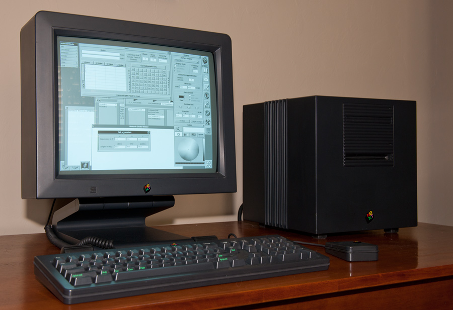
Not only is Doty an RF guru, he uses (used?) a NeXT computer, a clear sign of superior intelligence ;-).
While I’m at it, I should also give some credit to John Bryant, Bill Bowers and Nick Hall-Patch: Their article on antenna impedance matching is here.