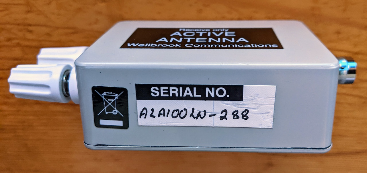
I’ve had a Wellbrook ALA100LN active loop antenna for quite a while. This is a variant of Wellbrook’s more popular ALA1500 series of small active loop antennas that became famous in MW DX circles in the late 1990’s and early 2000’s.

The difference between the ALA100 and the ALA1500 series is that for the ALA100, you provide your own loop in the form of 5-10 meters of wire (although some use considerably more than that), and as a result you also have to provide some mechanism to hold that wire up in the air in a vauguely loop-like shape (i.e. square, circle, triangle, rectangle, etc.).
Living as I do on a lot full of Fir trees that are 80-100 feet tall, of course I wanted to hang said loop up as far up as I could. On my first attempt, I managed to get it up about 65-70 feet. This was fine, but one caveat about hanging antennas from trees like these is that the tops of the trees move around in the wind. A lot, like 10-15 feet, and often the tops of two trees will be seen to be moving in opposite directions.
My first attempt at hanging up the loop came crashing down last winter as the wire in the loop just pulled completely apart. I’d been procrastinating on getting it fixed until this past summer. This time I took more care, and made sure that:
- The wire loop was not the structural support for the loop; a dacron rope across the top is the structural support and the loop just hangs from it.
- The other tree has a rope with an eyelet thrown over it.
- The dacron rope is fixed only on one tree; the other side of the rope goes through the eyelet on the rope fixed to the other tree, allowing the rope supporting the loop to slide back and forth through the eyelet.
This all seemed to be working fine, and after a couple of storms during the past month, the loop was still in place and unperturbed.
So I decided it was time to reconnect the Wellbrook in my shack, so this afternoon I set out to perform that task, which should have only taken 10 or 15 minutes. Famous last words.
For testing, I connected the power injector/antenna interface to my Icom IC-705. Once I connected the Wellbrook-supplied AC “wall wart” adapter to the interface to power up the active loop, I was dismayed to see S-9 broadband “hash” all across HF, from 80M to 10M (and probably beyond, I did not look).
After scrambling around to find some cleaner power source, I hooked up the Wellbrook to my trusty ancient linear 12V power supply. The result was the same. After a brief interlude to walk the dog, I got serious and took the Icom IC-705, the Wellbrook antenna interface, a 12 volt Gel-cell battery, and some cables outside and connected things directly to the cable that goes out to the loop (I have a “stub” cable that goes through the wall of my house that I was suspicious of). Sadly, the results were the same, broadband hash everywhere, and notably, still present at a lower amplitude if power was removed from the loop.
A quick search of Google in hopes of finding others who might have suffered the same fate yielded a message on the Loopantennas Groups.io e-mail list. In that message, the late Andy Ikin, the creator and proprietor of Wellbrook Antennas stated the following:
The issue you mention can be applicable to any active antenna which is voltage fed via the feeder cable. The problem is caused when moisture gets into the feeder BNC connector and a conductive residue forms across the connexion due to electrolytic action with the dc voltage. This generates considerable noise when the voltage is applied. In some cases the noise problem doesn’t show up if the feeder is then used with a passive antenna. Hence, this can lead to a false diagnosis that the antenna is faulty.
If the antenna connectors are covered in either Vaseline or Dow Corning DC 4 grease and a PVC boot is slid over the connectors, this should be okay.
So, I treked out to the backyard and undid my various ropes and lines to get the loop down to arm’s reach and checked the connection. Sure enough, the BNC connector to the amplifier box was “unclicked”, not fully engaging the detent at the bottom of the BNC connector collar (it is unfortunate that Wellbrook used BNC connectors, rather than the venerable CATV type F connectors which are widely used and easy to make mechanically strong and weatherproof).
I fetched an additional zip-tie and some 3M electrical tape, and tightened up the BNC connector, taped it into place and added the zip tie to keep the amplifier box centered under the insulator at the bottom of the loop.
I ran back into the house and was relieved to see that while the antenna was relatively noisy compared to some of my other passive wire antennas, there was no longer an S-9 hash everywhere.
I have to admit that I was also relieved that apparently nothing had gone wrong with Andy’s elegant super-low-noise, super-low-impedance preamplifier as it is encased in epoxy, and like Andy, any hope of replacements or repair is long gone. A snippet from an ancient version of his (Wellbrook) website:
The new JFET design affords a considerable reduction of noise compared to low cost loops using MMIC (Monolithic Microwave Integrated Circuit). MMICs are designed for Microwave use and therefore are unsuitable for LF to HF loops. Furthermore, MMICs use integrated resistor feedback, which limits the noise figure to a minimum 3dB at HF. At Medium Frequencies loops using MMIC amplifiers can have a Noise Figure as high as 8dB plus high IMD (Intermodulation Distortion).
The FLX1530LN has a noise figure of approximately 0.2dB, which give a noise floor that is 13dB lower compared to a similar gain loop with a noise figure of 3dB.
This antenna and ALA1530LN are the only 1m dia. active loops in production that use an ultra low noise JFET design.
The new FLXALA1530LN and the ALA1530LN are the second generation of loop antennas to come out from the Wellbrook stable. The design comprises of 8 very high gain JFETs in parallel push-pull with a Bipolar transistor cascode stage to extended bandwidth. A very low amplifier noise floor is achieved by dynamically decreasing the JFET Source resistance to a fraction of an Ohm. This is achieved using a proven technique developed by Dr. Ulrich L. Rohde in the 1970s by coupling the FET Gate to the Source with a phase inverting transformer.
The loop works by designing amplifier so that the very low noise of the loops real resistance is mismatched to the input impedance of the low noise amplifier. Hence, reducing the amplifier noise floor by up to 13dB compared to more conventional low noise amplifiers. Also JFETs are less noisy at low frequencies compared Bipolar transistors. The amplifier also has rising input impedance versus frequency to match the loop’s reactance; this together with Ultra low noise JFET design is a technological breakthrough.
In their time, the Wellbrook loops were unmatched, and so far, nothing has come along to replace them.
