
Given that most hams suffer to some degree of self-inflicted QRM caused by their own equipment and wiring, many are naturally quite interested in information and advice about how to find and mitigate this problem.
Noted Authorities
Two notable authors on this topic are Ward Silver, N0AX, who wrote a whole book for ARRL about bonding and grounding: “Grounding and Bonding for the Radio Amateur”, and James W. Brown, K9YC, who has written and published a number of detailed articles at his website regarding grounding, bonding, noise mitigation and related topics, including one entitled “Power, Grounding, Bonding, and Audio for Ham Radio - Safety, Hum, Buzz, and RFI”.
The Problem
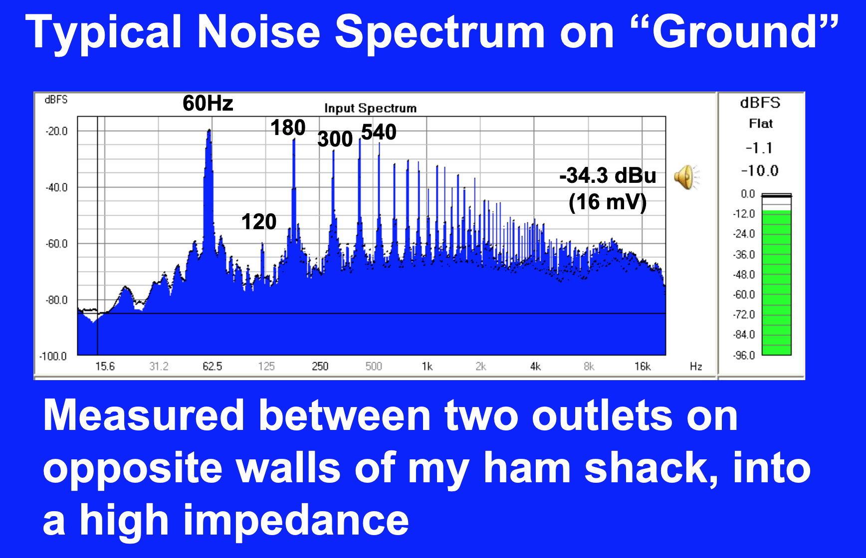
The basic problem is that for almost all typical amateur radio equipment, the connections between various pieces of equipment are made with unbalanced connections, which means that signals are carried between devices as a voltage working against a common ground. The issue is that the common ground is not common, and it is easy to measure voltage differences between ground at one device and ground at another device.
The Solution
The two authors suggest different solutions to this problem:
Ward Silver, N0AX
N0AX suggests the following:
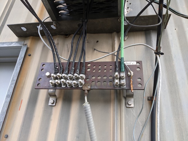
A practical and effective alternative is to provide a wide and flat or round conductor at the back of the equipment. (See Figure 4.19 in the previous chapter.) This creates a bonding bus. The bus can be any large conductor. A short length of copper pipe is inexpensive and a popular choice although large wire or strap can also be used. You can sometimes find surplus bus bars in scrap metal yards, too. Connection points can be pre-drilled in the bus and left open or a screw can be installed for later use. The enclosures of each piece of equipment, including computers and other non-radio electronics, is then connected to the bus with a bonding jumper: short, heavy wire or strap. Stranded wire is fine and is flexible enough to allow the equipment to be moved or repositioned. Use crimp terminals or ground clamps to connect the bonding jumpers to the bus. It should be noted that while more convenient, use of a bus makes the bonding path longer and somewhat less effective at reducing power frequency noise.[1]
James W. Brown, K9YC
Whereas K9YC makes the following statement:
Single-Point Madness
- Virtually all interconnects are unbalanced, tie chassis to chassis
- We may call them an audio cable or computer or “coax between rig and amp,” but Mother Nature sees their shields as part of a big loop with star bonding conductors
- Most equipment has a Pin One Problem
- Current in the loop gets inside our gear
- Hum, buzz, RFI, lightning damage
- Ground bar at back of desk is a bad idea
- Individual bonds from each piece of gear to a common ground inside or outside the shack is a bad idea
- Greatly increases resistance between interconnected equipment
- More power line buzz
- Creates loops for magnetic coupling[2]
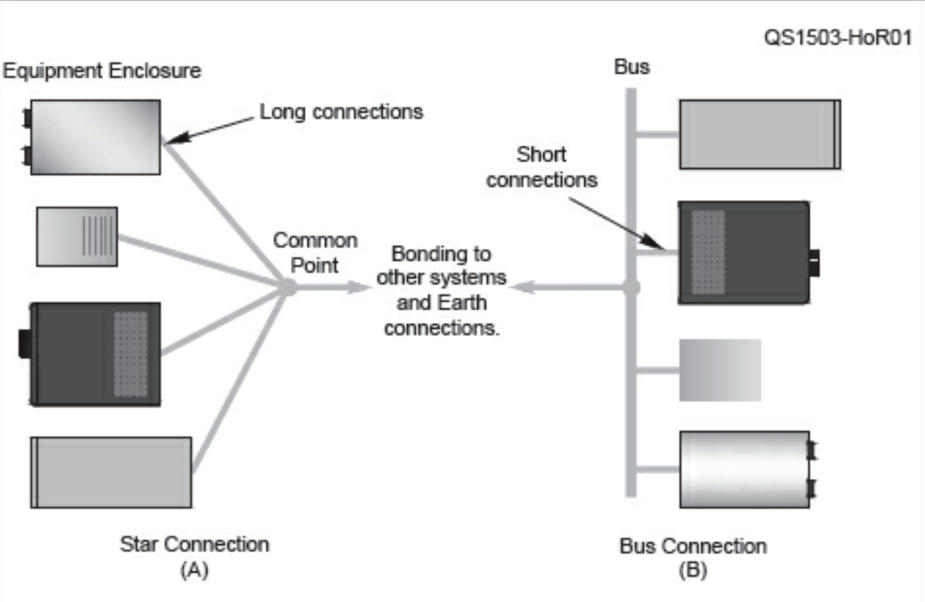
While Silver references and acknowledges Brown’s works in his book, his argument for using a bonding bus seems to be related to practical considerations, whereas Brown’s repudition of this practice seems to be related to the fact that it prevents keeping the bonding connections between equipment to the absolute minimum length.
This leads to the question: Who’s right?
References
- ARRL Inc.; Silver (N0AX), Ward. “Grounding and Bonding for the Radio Amateur”. ARRL, the national association for Amateur Radio. Kindle Edition.
- “Power, Grounding, Bonding and Audio for Ham Radio”, pages 112-113, retrieved 2022-02-13